
Introduction
The distance between a brilliant industrial concept and a profitable physical product is measured in the precision of its engineering blueprints. In the heavy manufacturing sector, vague schematics do not just cause minor delays; they result in catastrophic machining errors, wasted raw materials, and completely stalled assembly lines. Relying on isolated draftsmen who do not understand the physics of the actual factory floor is a massive financial liability. By utilizing the Crinfly Ecosystem for your engineering design and drafting, you ensure that every 3D CAD model is perfectly engineered for manufacturability, seamlessly integrating with your automation hardware and accelerating your overall business growth.
Buyer Intent Block
Definition
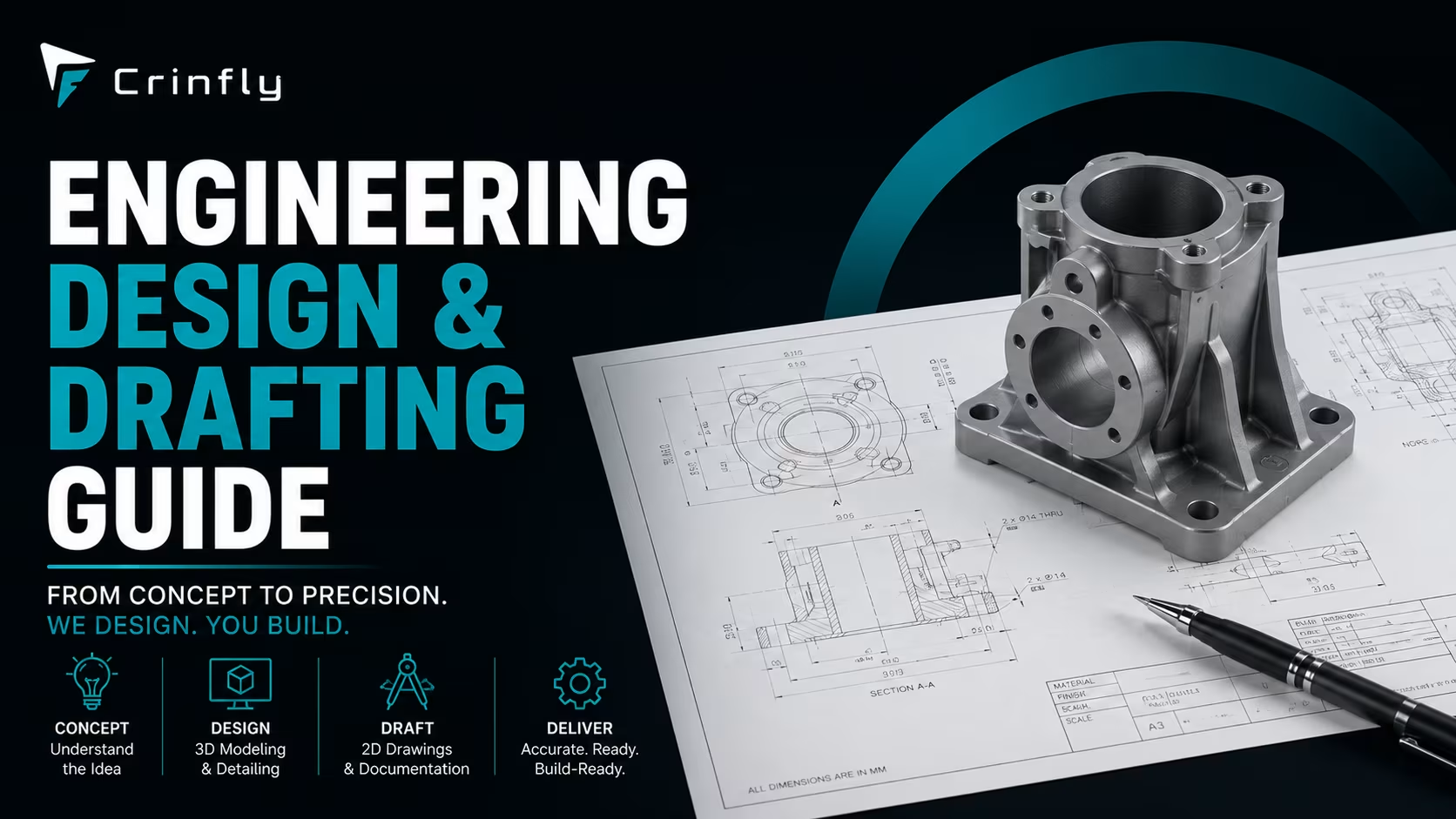
Engineering design and drafting is the highly technical process of creating precise 2D blueprints, 3D CAD models, and GD&T (Geometric Dimensioning and Tolerancing) specifications required to safely and profitably manufacture a physical product or machine.
Quick Answer
To successfully execute engineering design, you must move beyond basic 2D drawings and utilize 3D modeling, ensuring strict adherence to Design for Manufacturability (DFM) principles so the product can actually be built by your factory machinery.
Expert Tip
Never send a blueprint to the factory floor without first having a senior CNC machinist review the tolerances. Engineers often design tight tolerances that look great on a screen but multiply production costs by 500% when physically machined.
Decision Rule
If your manufacturing floor is experiencing a scrap rate above 4% due to misaligned parts, you must immediately halt production and execute a comprehensive audit of your original engineering drafts.
Warning
Outsourcing your engineering drafting to generic, low-cost CAD freelancers often results in non-compliant files that violate regional safety standards and lack critical material stress-test data.
Best Practice
Always align your engineering output with your industrial marketing. High-quality 3D renders generated during the drafting phase should be given immediately to the marketing team to presell the product before it is even manufactured.
Table of Contents
- Bridging the Gap Between Concept and Reality
- The S.H.A.P.E. Design Framework
- Comparison: 2D Legacy Drafting vs. 3D Digital Ecosystems
- Step-by-Step Engineering Drafting Guide
- Current Trends in Engineering Design
- 5 Common Drafting Mistakes
- Key Facts at a Glance
- Frequently Asked Questions
Bridging the Gap Between Concept and Reality
Quick Answer
Modern engineering drafting acts as the universal translator between the creative ideation of industrial designers and the absolute physical constraints of factory floor machinery.
Why It Matters
If a product is designed without considering how the robotic arms or CNC routers will physically interact with it, the manufacturing cycle time will be cripplingly slow, entirely destroying your profit margins.
Expert Insight
I frequently see startups burn millions of dollars in venture capital because they finalized a beautiful CAD design without performing a Finite Element Analysis (FEA). When the product finally hit the testing phase, the structural integrity failed, forcing them to start over from scratch.
Detailed Explanation
Engineering design is not about drawing pictures; it is about simulating physics. A proper drafting process incorporates material science, thermodynamics, and fluid dynamics. It dictates not just the shape of the part, but exactly what type of steel is required, how it must be welded, and what post-processing treatments are legally necessary to meet compliance standards (like ASME or ISO).
Real Example
An agricultural machinery company was struggling to assemble a complex gearbox because the internal gears kept clashing. A Crinfly engineering consultant audited their CAD files and realized the drafts lacked proper GD&T (Geometric Dimensioning and Tolerancing) callouts. By simply updating the tolerances on the blueprints, assembly time dropped from four hours to 45 minutes.
Business Application
Use your highly precise engineering drafts as intellectual property (IP) assets. By documenting your proprietary designs meticulously, you drastically increase your company's valuation during mergers and acquisitions.
Key Takeaway
Treat your engineering drafts as the legal contract between your vision and your factory floor. Vague contracts lead to costly disputes.
The S.H.A.P.E. Design Framework
To guarantee that a design can be manufactured profitably at scale, the Crinfly Ecosystem utilizes the proprietary S.H.A.P.E. engineering framework.
- Simulate: Before drawing final lines, use physics engines to simulate the stress, heat, and load the product will endure in the real world.
- Harmonize: Align the design with the specific capabilities of your factory. Do not design a part that requires 5-axis milling if your factory only owns 3-axis machines.
- Analyze (DFM): Conduct a strict Design for Manufacturability review. Remove any unnecessary curves, undercuts, or custom hardware that bloats the production cost.
- Prototype: Generate a rapid 3D printed or low-fidelity prototype strictly to test physical ergonomics and assembly fitment.
- Execute (Drafting): Lock the design and generate the final, hyper-detailed 2D manufacturing drawings with exact GD&T callouts for the machine operators.
Comparison: 2D Legacy Drafting vs. 3D Digital Ecosystems
| Feature | Legacy 2D Drafting (AutoCAD) | 3D Digital Ecosystems (SolidWorks/NX) |
|---|---|---|
| Cost Structure | Low software cost, high error correction cost | High software cost, massive error prevention savings |
| Clash Detection | Manual; highly prone to human oversight | Automated; software physically prevents overlapping parts |
| Simulation | Impossible; relies on theoretical math | Native; executes FEA and thermal simulations instantly |
| Scalability | Requires redrawing for every size variation | Parametric; changing one variable automatically scales the rest |
| Automation Readiness | Cannot be fed directly to CNC or robotic CAM software | Generates direct G-Code for automated manufacturing machinery |
| Complexity | Difficult for non-engineers to visualize | Generates photorealistic renders for marketing and sales |
| Risk | High risk of misinterpretation by the factory floor | Low risk; 3D models leave no room for ambiguity |
| Best Use Case | Simple electrical schematics or floor plans | Complex mechanical assemblies, heavy machinery, consumer goods |
Step-by-Step Engineering Drafting Guide
- Concept Finalization: Lock down the core requirements, including target production cost, expected lifespan, and regulatory standards.
- Parametric 3D Modeling: Build the digital part using parametric CAD software, ensuring that future dimensional changes will auto-update associated features.
- Digital Stress Testing (FEA): Run Finite Element Analysis on the 3D model to identify structural weak points and optimize the material thickness.
- Design for Assembly (DFA): Review the model to minimize the total part count. If two parts can be combined into a single injection-molded piece, combine them.
- Generate 2D Manufacturing Prints: Extract 2D views from the 3D model. Add strict GD&T (Geometric Dimensioning and Tolerancing) to dictate exact acceptable deviations.
- Bill of Materials (BOM) Generation: Create a comprehensive list of every screw, bearing, and raw material block required to assemble the product.
- CAM Integration: Export the files in standard formats (STEP, IGES) directly to the factory floor's Computer-Aided Manufacturing (CAM) software to begin automated cutting.
Current Trends in Engineering Design
Quick Answer
Modern engineering departments are leveraging Generative AI Design, cloud-based collaborative CAD platforms, and direct integration with 3D printing ecosystems.
Why It Matters
Competitors using Generative Design can create lighter, stronger parts in a fraction of the time it takes a human engineer to calculate the geometry. Adopting these tools is necessary to remain competitive in B2B bidding.
Expert Insight
Generative design flips the script. Instead of the engineer drawing the part, the engineer inputs the constraints (e.g., "It must hold 500 lbs, use aluminum, and bolt to these four points"). The AI then generates 100 potential geometric solutions, often resembling organic, bone-like structures that a human would never conceive.
Detailed Explanation
The shift to cloud-based CAD (like Fusion 360 or Onshape) has eliminated the siloed engineering department. Now, a mechanical engineer in the USA can tweak a dimension, and the manufacturing floor in India sees the updated blueprint in real-time. This eliminates the massive delays caused by emailing outdated PDF blueprints back and forth.
Real Example
An aerospace supplier utilized AI Generative Design to redesign a seat bracket. The AI algorithm removed material where there was zero structural stress, resulting in a bracket that was 40% lighter but retained the exact same load-bearing capacity, saving the airline millions in fuel costs over the fleet's lifetime.
Business Application
Promote your advanced engineering capabilities to procurement managers. Buyers want to know that their suppliers are actively optimizing designs to save them money.
Key Takeaway
Engineering drafting is no longer just about recording a design; it is about actively using AI and cloud data to mathematically perfect the design.
5 Common Drafting Mistakes
- Mistake 1: Ignoring Standard Hardware. Why it happens: Engineers want the perfect aesthetic. Impact: Designing a custom screw thread costs $50 per unit instead of using a standard $0.05 off-the-shelf bolt. How to avoid it: Mandate the use of standard McMaster-Carr or global hardware catalogs.
- Mistake 2: Over-Tolerancing. Why it happens: Fear of part failure. Impact: Specifying a +/- 0.001 inch tolerance on a part that only needs +/- 0.05 inches forces the factory to use expensive, slow machining methods. How to avoid it: Apply tight tolerances strictly to the specific mating surfaces, not the entire part.
- Mistake 3: Designing Blind to Machinery. Why it happens: Lack of factory floor experience. Impact: The engineer designs an internal pocket with a sharp 90-degree corner, which a spinning round CNC drill bit physically cannot cut. How to avoid it: Enforce the S.H.A.P.E. framework's harmonization step.
- Mistake 4: Poor Revision Control. Why it happens: Saving files as "Final_Final_v2.pdf". Impact: The factory machines 10,000 parts based on last week's outdated blueprint. How to avoid it: Implement a rigid Product Data Management (PDM) software system.
- Mistake 5: Failing to Draft for Packaging. Why it happens: Tunnel vision on the core product. Impact: The product works perfectly but does not fit into standard shipping pallets, doubling freight costs. How to avoid it: Consult with the packaging department before locking the final CAD dimensions.
Key Facts at a Glance
- Definition: Engineering design and drafting translates conceptual product ideas into strict mathematical blueprints executable by factory machinery.
- Best Practices: Always run a Finite Element Analysis (FEA) on structural components before creating the 2D manufacturing prints.
- Decision Criteria: Outsource your engineering to an industrial consultancy if your internal team lacks specific knowledge of Design for Manufacturability (DFM).
- Checklist: Finalize concept, build parametric 3D model, run simulations, apply GD&T, generate the BOM, and sync with the factory floor CAM software.
- Summary: Flawless engineering drafting eliminates manufacturing friction, ensuring products transition from a digital screen to a physical assembly line profitably and safely.
Frequently Asked Questions
What is the difference between 3D CAD modeling and 2D drafting?
3D CAD (Computer-Aided Design) is the creation of a complete, virtual, three-dimensional solid model of the product. It calculates mass, center of gravity, and allows for physics simulations. 2D drafting is the extraction of flat, technical drawings from that 3D model. The 2D drafts contain the specific dimensions, tolerances, and notes that the human machinist needs to actually cut the metal.
What is GD&T and why is it mandatory for manufacturing?
GD&T (Geometric Dimensioning and Tolerancing) is an international language of symbols used on engineering drawings. It does not just tell the machinist the size of a hole; it tells them exactly how perfectly round the hole must be, and how perpendicular it must be to the base surface. Without GD&T, a factory could legally manufacture a part that meets your basic dimensions but is completely warped and unusable.
Can we go straight from 3D CAD to manufacturing without 2D prints?
In highly advanced, fully automated Industry 5.0 ecosystems, Model-Based Definition (MBD) allows the CNC machines to read tolerances directly from the 3D file. However, for 90% of global manufacturing, 2D prints are still legally and operationally required. They act as the inspection standard for the Quality Assurance (QA) team and the contract document for external vendors.
How does engineering design impact the cost of my product?
Over 70% of a product's final manufacturing cost is permanently locked in during the engineering design phase. If the engineer selects titanium instead of aluminum, or specifies a shape that requires slow 5-axis machining instead of fast injection molding, the cost skyrockets. This is why Design for Manufacturability (DFM) consultation is the highest ROI investment a company can make.
Why do we need a Bill of Materials (BOM) if we have the drawings?
The engineering drawings tell the factory how to make the custom parts, but the BOM tells the procurement team exactly what to buy to assemble it. A complete BOM lists every single raw material block, standard screw, electronic sensor, and zip tie required. Without a perfectly accurate BOM, the assembly line will inevitably halt due to missing minor components.
How do we protect our intellectual property when sending drafts to overseas factories?
Never send the complete, fully assembled 3D native CAD files (like a raw SolidWorks file) to a single external vendor. You should only send non-editable, "dumb" solid files (like STEP files) of individual components, or PDF 2D prints. Furthermore, split the manufacturing; have Vendor A make the housing and Vendor B make the internal mechanism, conducting final assembly domestically to protect the complete IP.
What is FEA (Finite Element Analysis) and when is it necessary?
FEA is a digital physics simulation. The software breaks the 3D CAD model into millions of tiny mathematical "elements" and applies virtual pressure, heat, or vibration. It is absolutely necessary for any load-bearing part, safety equipment, or high-speed machinery component. It proves the part will not snap under pressure before you ever cut a piece of physical metal.
How long should the engineering drafting process take?
The timeline varies wildly depending on complexity. A simple mechanical bracket might take two days to model and draft. A complete automated packaging machine could take 6 to 12 weeks of continuous engineering. Rushing the drafting process to save time upfront is the most common cause of multi-month delays on the factory floor.
What happens if the factory floor cannot manufacture our design?
If the design violates physics or the factory's machine capabilities, it triggers an Engineering Change Order (ECO). The factory must stop, request a change, the engineer must update the 3D model, update the 2D draft, update the BOM, and reissue it. This cycle is incredibly expensive and is entirely prevented by utilizing the S.H.A.P.E. framework's harmonization step early on.
Why is reverse engineering sometimes required for older machinery?
Many factories run legacy equipment built in the 1990s where the original paper blueprints have been lost. If a critical gear breaks, you cannot order a new one. Reverse engineering involves using 3D laser scanners to measure the broken part and creating brand new, modern 3D CAD models from those measurements so a replacement part can be instantly CNC machined.
Should we design custom components or use off-the-shelf parts?
You should aggressively favor off-the-shelf (COTS) parts for everything except the core proprietary function of your product. Using a custom thread size for a bolt adds zero value to the customer but adds massive manufacturing cost and supply chain risk. Reserve your custom engineering hours strictly for the features that differentiate your product in the market.
How does engineering design interact with industrial marketing?
Marketing cannot sell a product effectively if they don't have visuals. High-end parametric CAD software can output photorealistic 3D renders and exploded-view animations of the product months before physical manufacturing begins. Your industrial branding team uses these assets to secure pre-orders and validate market demand, entirely de-risking the product launch.
Conclusion
Engineering design and drafting is the absolute foundation of all industrial success. Treating it as a simple drafting exercise ignores its true power: it is a financial control mechanism that dictates the profitability, safety, and scalability of your final product. By demanding 3D digital environments, rigorous physical simulations, and deep harmonization with the factory floor through the S.H.A.P.E. framework, manufacturers eliminate guesswork. Ultimately, an integrated engineering approach ensures that your visions transition seamlessly from the digital screen to the physical market, driving unstoppable growth.
Call to Action
Do not let flawed blueprints bottleneck your factory floor. Partner with the Crinfly Ecosystem today to secure world-class engineering design and drafting. Let our senior engineers optimize your CAD models for manufacturability and profitability.